
Read through this page and try some quizzes.
 Chapter 1
What is
Strain?
A strain is a quantity of the deformation - elongation or contraction of a
material in proportion to applied external force.
Strain gage detects this strain as an electrical signal.
There are various structures made of different materials in varied sizes and shape.
They include transports such as automobiles, aircrafts, railway vehicles and ships, and civil
engineering and building constructions such as dams, bridges, and skyscrapers. Measurement of
“stress,” which is a criterion of the strength of these structures operating under severe
conditions, is indispensable for assurance of the strength and safety.
It is indispensable to know the stress to investigate an optimum design for satisfying the
embodiment of a unique idea, lighter structure or selection of a suitable material and the assurance
of the strength and safety.
Recently, computer-aided stress analysis techniques have been developed and introduced in the design
field. However, experimental stress measurements with strain gages are widely used as the surest and
practical method even now.
Strain = Quantity of the deformation – elongation or contraction of a material.

 Chapter 2
Principles of Strain Gages
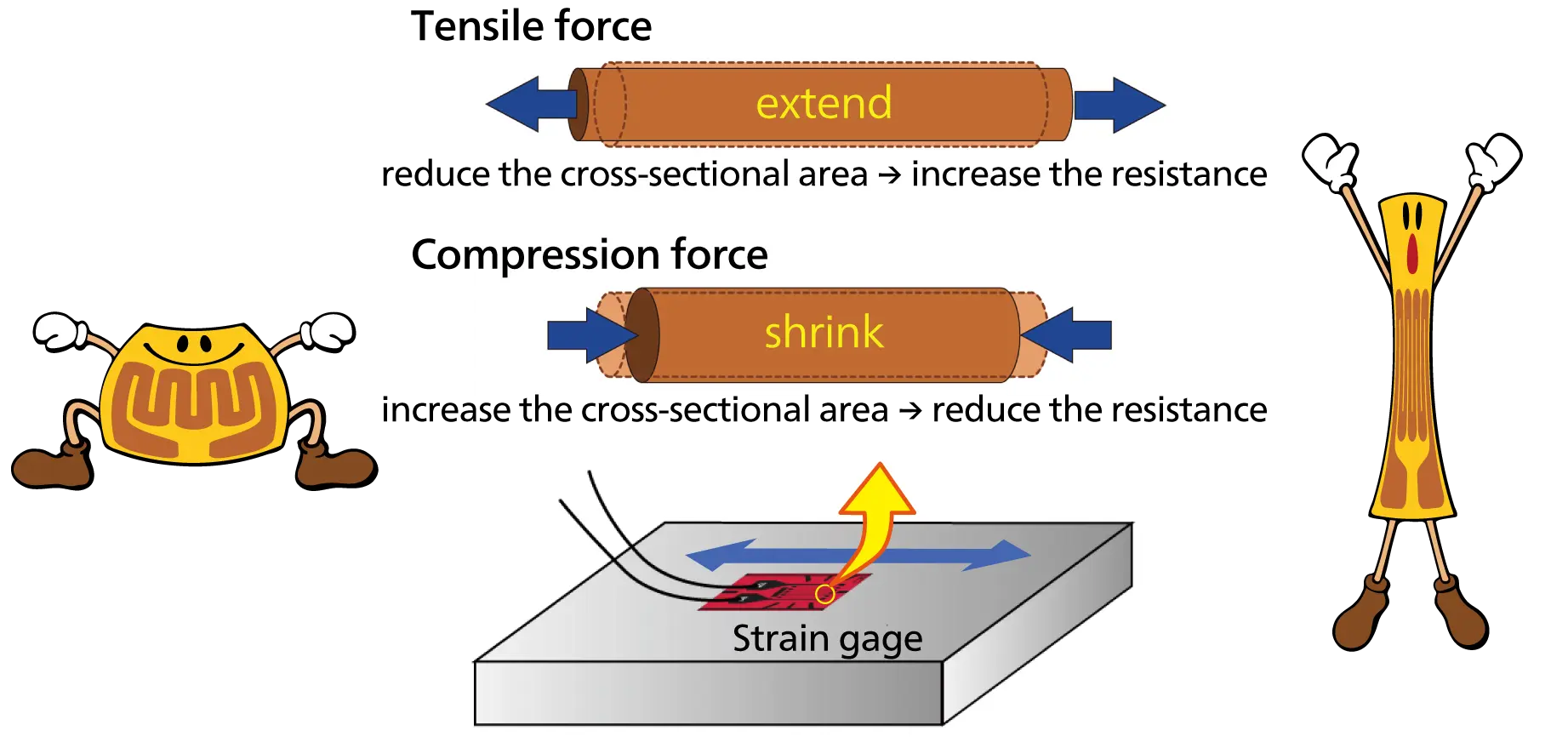
Metal changes its electrical resistance as it deforms. Strain gages take
advantage of this property.
The amount of electrical resistance is in inverse proportion to the cross-sectional area and is
proportional to the length.
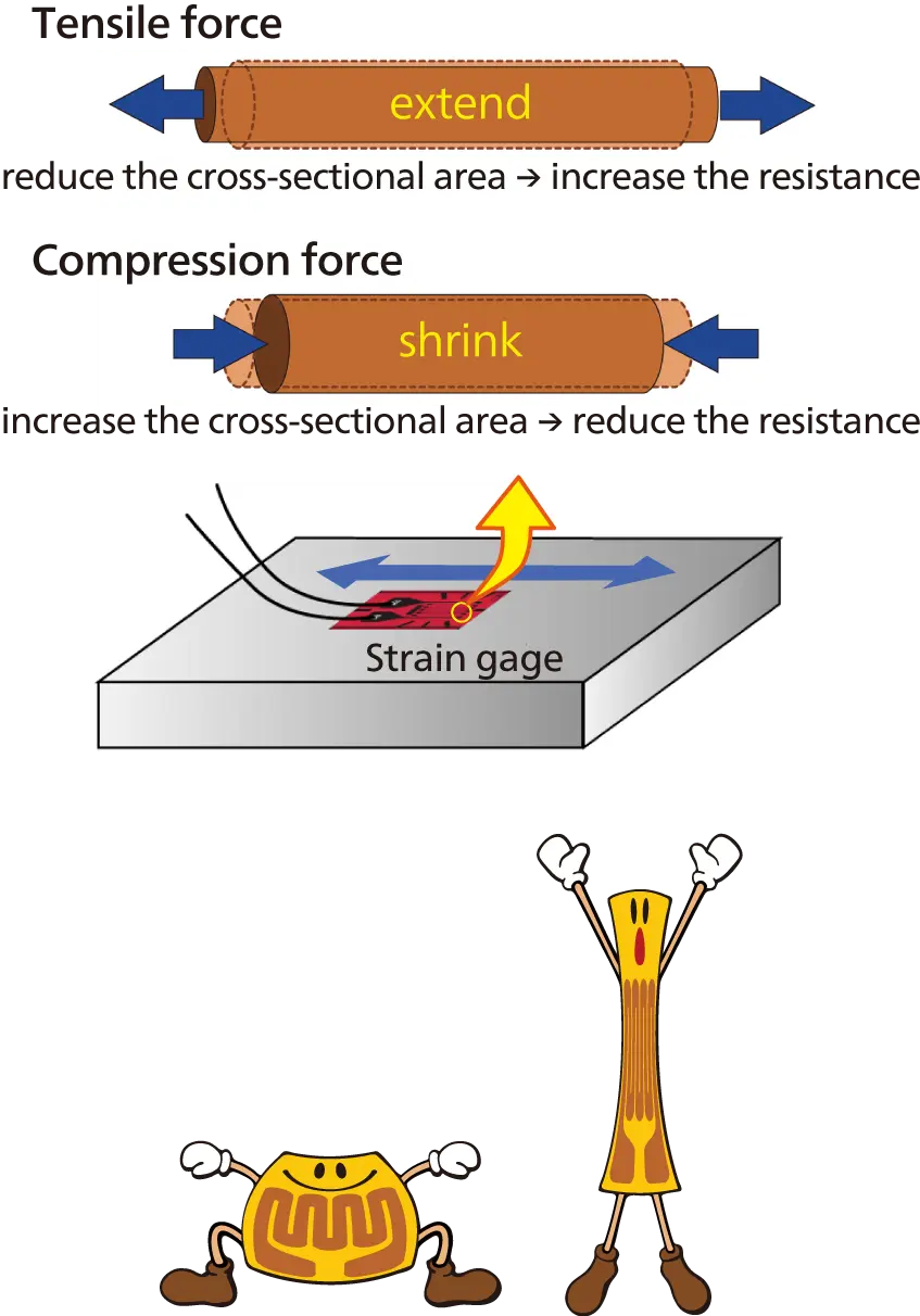
If a metal wire is pulled, the cross-sectional area becomes smaller, and the length becomes longer,
thereby making the resistance larger.
If the metal wire is compressed, the electrical resistance becomes smaller.
Elongation or shrinkage proportionally changes the electrical resistance of metal with the specific
constant.
If the metal wire is bonded to the target structure, it elongates or shrinks as the structure
elongates or shrinks.
Thus, measurement of the changing electrical resistance of the metal wire enables detection of
elongation or shrinkage, i.e., “strain” of the structure.
Resistance changes of strain gages - bonded to the target object- are
extracted, converted to voltage and amplified.
To elongate or shrink the strain gages together with the measuring objects, bond them securely by
using the dedicated adhesive.
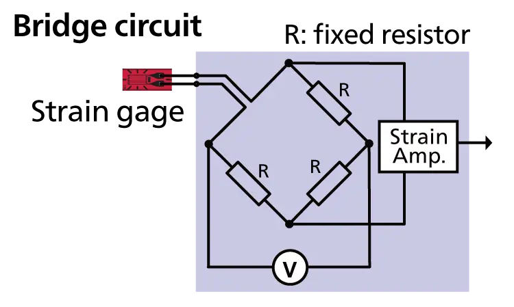
To accurately measure the electrical resistance change of the strain gage, form a bridge circuit to
convert the resistance change to voltage change.
Since the voltage is small as expressed in μV, it is usually amplified by 5000 to 10000 times.
 Chapter 3
Selecting Strain Gages
Our strain gages are easy to understand what kind of purpose or environment would
be appropriate by model names.
Select strain gage models and gage length that match the target object and purposes.
KFGS
Model Model
-
2
Gage length (mm) Gage length (mm)
-
120
Resistance (Ω) Resistance (Ω)
-
C1
Gage pattern Gage pattern
-
11
Applicable linear
expansion coefficient Applicable linear expansion
coefficient
L1M3R
Type and length
of lead-wire cable Type and length of lead-wire
cable


 Chapter 4
Bonding
Strain Gage
To obtain useful data, correctly bond strain gages to a measuring
object.
Thus, it is essential to select a suitable adhesive for the materials of the measuring object and
measuring conditions.
In case of a general stress measurement by using KFGS gages, the CC-33A instantaneous adhesive is
commonly used.
The CC-33A ensures smooth bonding works because of quick curing time.
It also enables measurement in approx. 1 hour after bonding.
 Chapter 5
Selecting Measuring Instruments
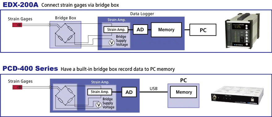
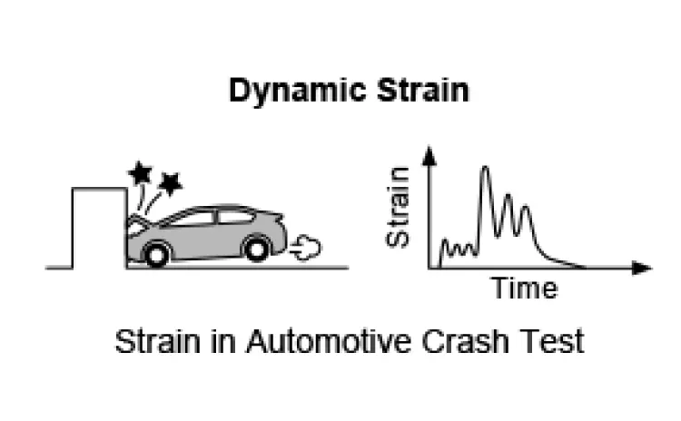
Our strain gages measure static strain and dynamic strain up to several hundred kHz
by shock or impact phenomena.
Depending on purposes, note that it is necessary to select an appropriate strain amplifier or data
logger.

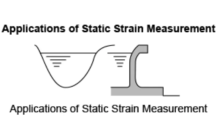
Static strain: Stable strain or strain which changes slowly.
Dynamic strain: Strain which changes rapidly.
Note that the border between static strain and dynamic strain are not defined clearly.
 Chapter 6
Measuring Strain
The relations between strain and strain gage output
Connect strain gages to an electric circuit which is called the Wheatstone Bridge. It is suitable
for detecting a slight change in resistance.
Suppose an original resistance of a strain gage is R (Ω) and a changed resistance due to elongation
or shrinkage is △R (Ω).
Calculate the strain ε by the following formula.


The “K” in above formula is called a gage factor, the coefficient expressing the
strain gage sensitivity.
The gage factor of general-purpose foil strain gage KFGS is approx. 2.
Suppose the bridge excitation voltage is E, strain gage resistance is R (Ω), and a changed
resistance due to elongation or shrinkage is △R (Ω).
Calculate the output voltage e (V) by the following formula.

The relations between strain and stress
It is challenging to know the stress of an object or a material directly.
Thus, we calculate stress by measuring the stress-based "strain."
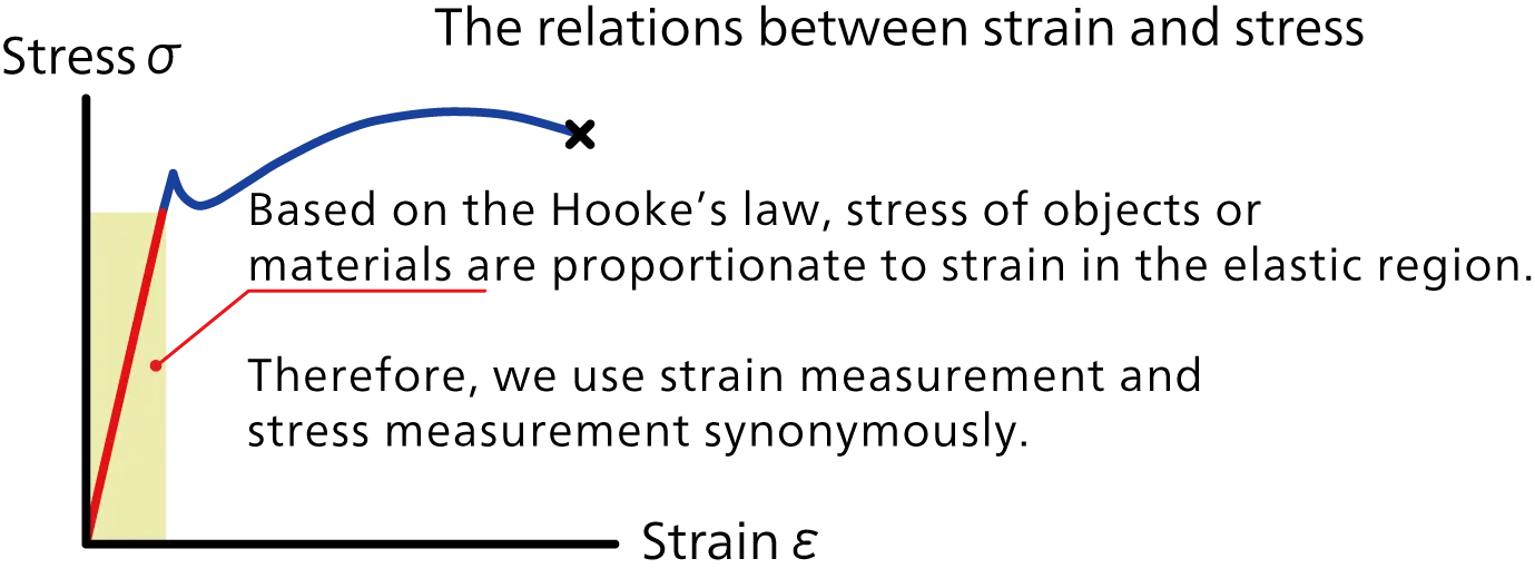
Based on the Hooke’s law, that stress is proportionate to strain in the elastic region, stress is
determined by measuring strain with strain gages.
Therefore, we often use strain measurement and stress measurement synonymously.

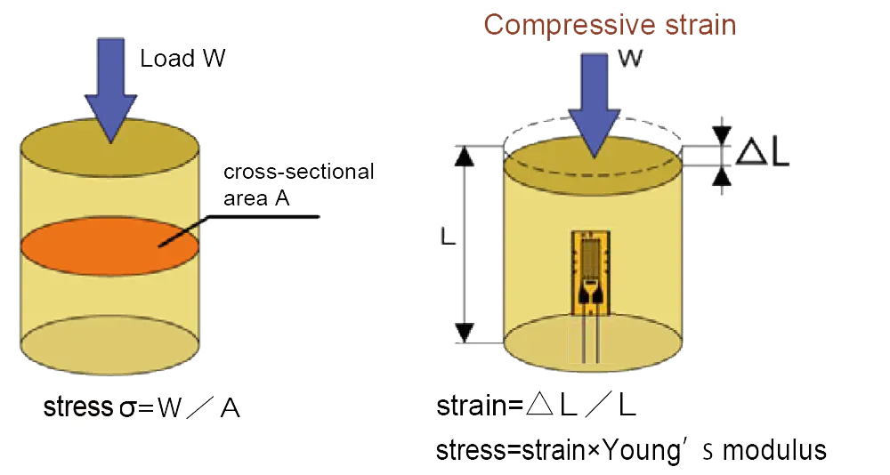
For this reason, when an amount of the applied force and cross-sectional area will
be known, stress can be calculated.
However, when the measuring object consists of complicated structures, complicated applied loads or
complex conditions, it may be challenging to calculate data with high accuracy.
Therefore, experimental stress measurements with strain gages are widely used as the surest and
practical method as verification of the safety structure design.
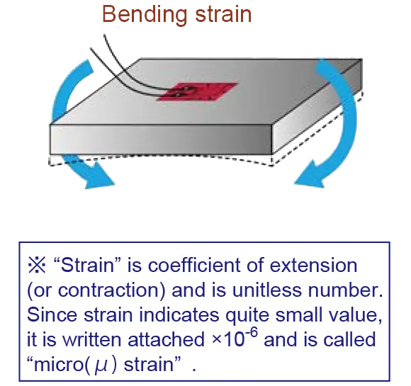
* "Strain" is a coefficient of elongation (or shrinkage) and is a unitless number.
Since strain indicates quite small value, it is written with "×10-6 strain" and
is called "microstrain."


Let’s check your understanding of basic strain gages.


